Converting GoPro telemetry into magnetic heading values to ensure videos are shown in 360 players facing the same direction as they were shot.
Last weeks post teased you with the mathematics that were ahead. Now that day has come.
In that post I wrote;
Using the
x,ycomponents of Magnetometer samples in addition to the roll and pitch angles calculated from theACCLsamples, we can calculate the absolute degrees the camera was facing from magnetic North (it’s heading).
So let’s start by calculating roll and pitch.
Calculation Roll, Pitch (and Yaw) from CORI samples
To calculate these values we take the four Quarternation values (Euler Parameters) and convert them into Euler angles on each axis.
Now the equations to do this are somewhat complex, as you’ll see from a cursory scan of this Wikipedia article; Conversion between Quaternions and Euler angles.
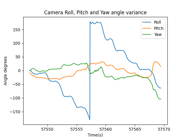
As we have data for all three axis it is possible to calculate yaw in addition to roll and pitch as pitch_x, roll_y, yaw_z in radians for every frame in the video (remember the sample rate for CORI data matches the framerate of the video).
Specifically for roll_y and pitch_x, the measurements in line with the way GoPro orientate the x and y axis;
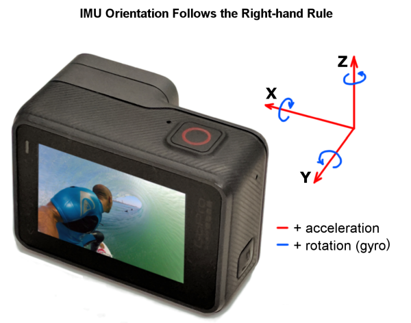
We can store this in a new stream value RPYR. We can also convert it to degrees knowing that 1Rad × 180/π = 57.296 degrees as a field RPYD.
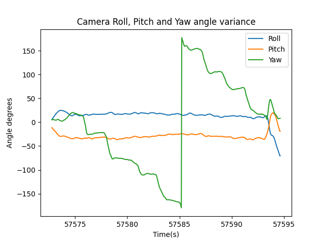
yaw_z calculated using this approach depends on the frame of reference where the sensor was initially calibrated from (at camera startup), it can tell the deviation in the angle from this reference but it does not necessarily account for magnetic angular deviation (in other words it does not ‘truly’ show the magnetic heading).
Therefore, we can also use the magnetometer samples (in addition to roll and pitch values just calculated) to better determine the heading.
Calculation Yaw from MAGN and CORI samples
Heading can be calculated by synchronising CORI and MAGN data. Before we jump into that, let’s first better understand the values for these fields.
The first challenge is the difference is sampling rates.
CORI reports samples at the same framerate the video was shot. The magnetometer MAGN samples are taken at an approximate frequency of 24Hz.
Therefore we first need to synchronise the sample times. A simple and crude way to do this (this is designed a proof-of-concept) is to find which CORI times each MAGN is closest too and assign that time to the value of the calculated heading.
For example, lets say we have a MAGN time equal to 2022-05-26T08:35:42.485Z and 3 CORI times, 2022-05-26T08:35:42.400Z, 2022-05-26T08:35:42.500Z, and 2022-05-26T08:35:42.600Z.
The closest CORI time to the MAGN time is 2022-05-26T08:35:42.500Z, therefore the MAGN timestamp is updated to consider this value.
Once the times have been synced and each MAGN sample has a corresponding CORI sample we can use calculate the magnetic heading.
Mx = mx * cos(p) + my * sin(p)
My = mx * cos(r) * sin(p) + my * cos(r) + mz * sin(r) * cos (p)
M_yaw = atan2(My,Mx)
Where:
mx= magnetometer x readingmy= magnetometer y readingmz= magnetometer z readingr= roll anglep= pitch angle
Be careful not to confuse My and my / Mx and mx (they are different variables). For clarity; my is the magnetic component in y direction, My is the output of the second equation which is approximately corrected y component of the magnetic field. The same explanation applies for Mx and mx.
We can store the M_yaw values in a new stream HEAR which reports the magnetic heading in radians, and HEAD which reports the magnetic heading in degrees.
In summary this gives us 5 new streams in the telemetry file
RPYR:- name: roll, pitch, yaw (y,x,z)
- units: radians
RPYD- name: roll, pitch, yaw (y,x,z)
- units: degrees
HEAR- name: magnetic heading
- units: radians
HEAD- name: magnetic heading
- units: degrees
Some examples
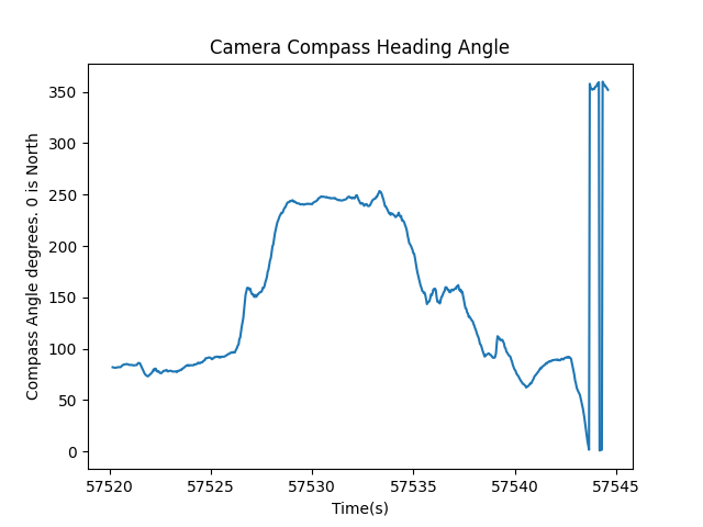
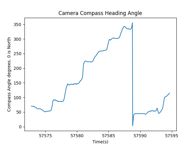
Let’s take a look at what this data looks like for some sample videos where I’ve deliberately exaggerated yaw, pitch and roll (sorry about the wind noise!).
You can download the files used here.
Pitch (x axis) change (GS010010.mp4)
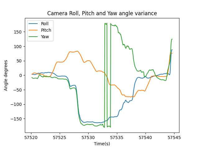
Roll (y axis) change (GS010011.mp4)
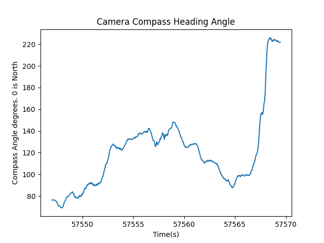
Yaw (z axis) change (GS010012.mp4)
In summary…
The HEAD value now reported for each frame tells us what compass direction the camera is pointing.
Next week I will use the calculated HEAD samples with an ffmpeg filter to dynamically adjust the yaw of our World Lock video (to reverse the World Lock effect).
We're building a Street View alternative for explorers
If you'd like to be the first to receive monthly updates about the project, subscribe to our newsletter...
