Understanding the geometry of an equirectangular image and training a computer to detect the horizon.
About a year ago, I briefly touched on how various projection types for 360 photos.
In todays post I am going to go deeper into the geometry of equirectangular projections as a way to idenfify roll mathmatically (and with the help of a computer).
The equirectagular planes
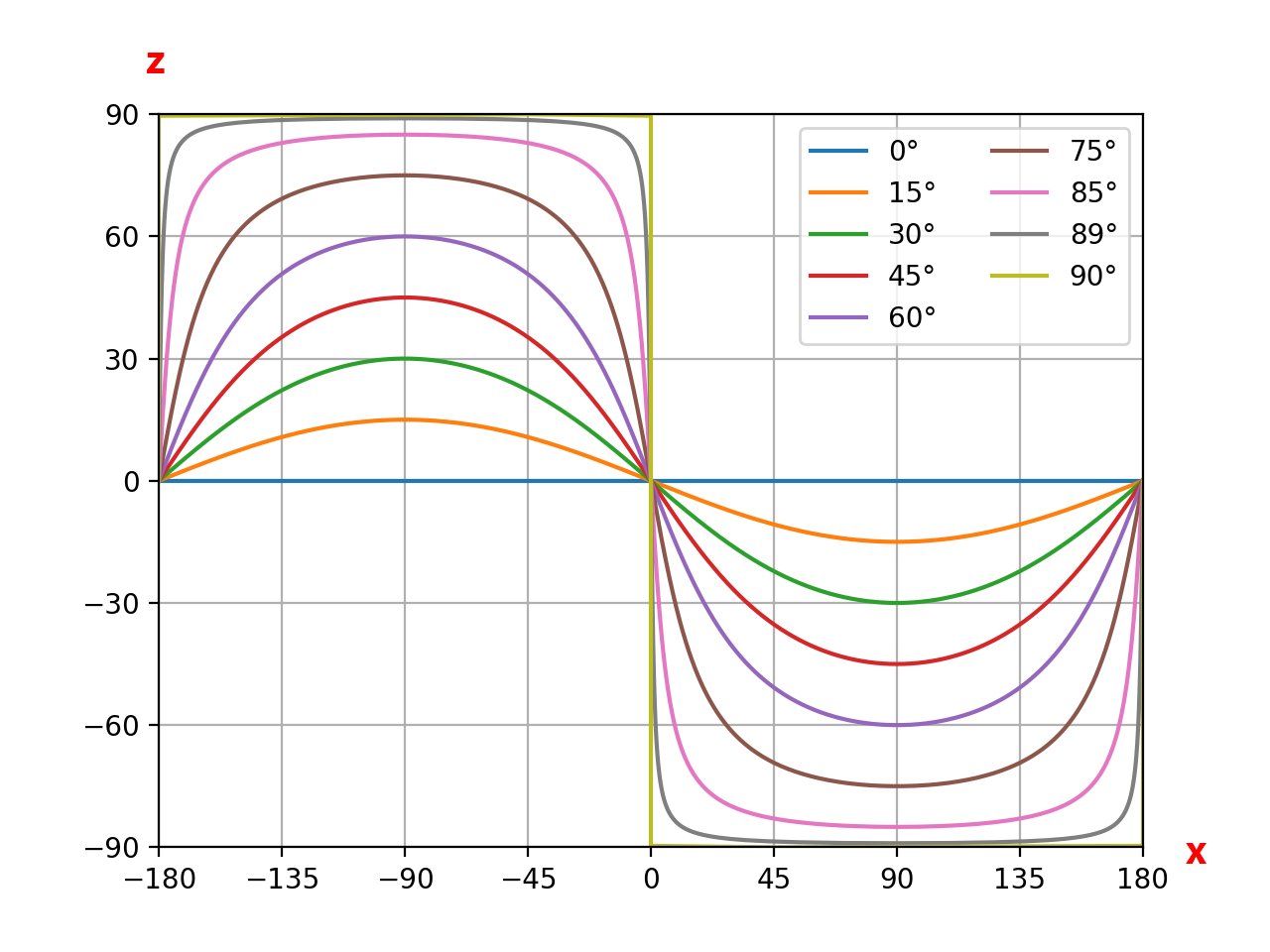
At the most simplistic level, when you look at an equirectangular image (as a flat image), the x axis is the longitude (left and right from -180 to 180) and the z axis is the latitude (vertically up and down from -90 to 90).
Note: Before we continue, it is important to remember that pitch is rotation around the x axis and yaw is rotation around the z axis. The x and z co-ordinates above do not give us either of those values. We are simply seeing
However, assuming the measurements relative to the photo (that yaw is 0 degrees and pitch is 0 degrees) we can estimate roll.
In the graph above you can see the waves representing roll (rotation around y). This is exactly the same as what I was showing last week.
The equation for roll (rotation around y) (assuming yaw is 0 degrees and pitch is 0 degrees)
y = arctan(tan(ROLL)sin(x))
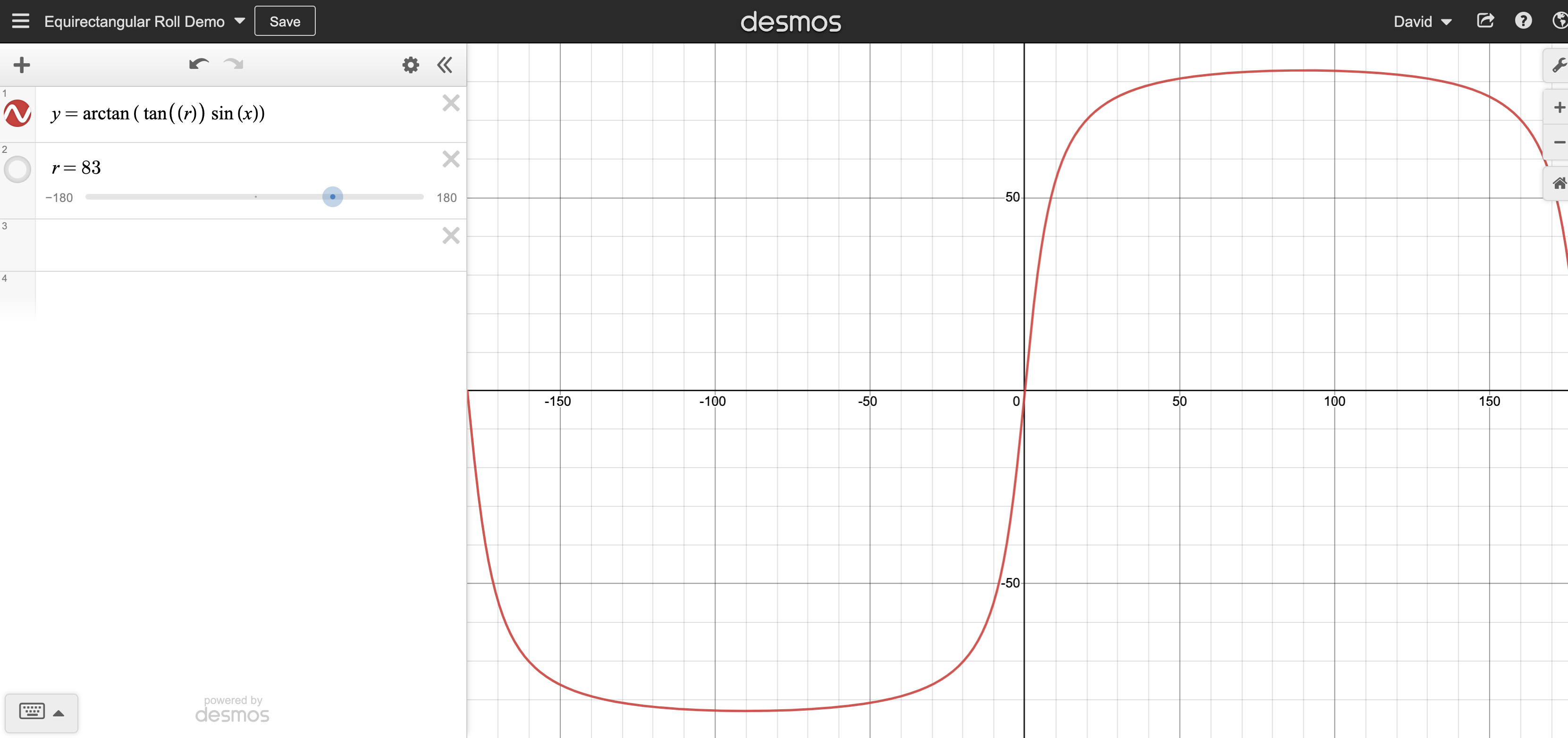
Have a play for yourself adjusting the roll value and watching how the modelled horizon changes.
Ofcourse, the visible horizon is not always going to be z=0, this requires further calculation to adjust, however, hopefully the general concept is clear.
Using a computer to draw the horizon
The next step in the process is to get a computer to idenfify;
- the horizon in the image, and
- identify the orientation of the camera (right way up or upside down)
I’ve talked a lot about the horizon. The orientation of the camera is important. You’ll notice that each roll horizon has two identical wave.
For example, when roll = 70 degrees;
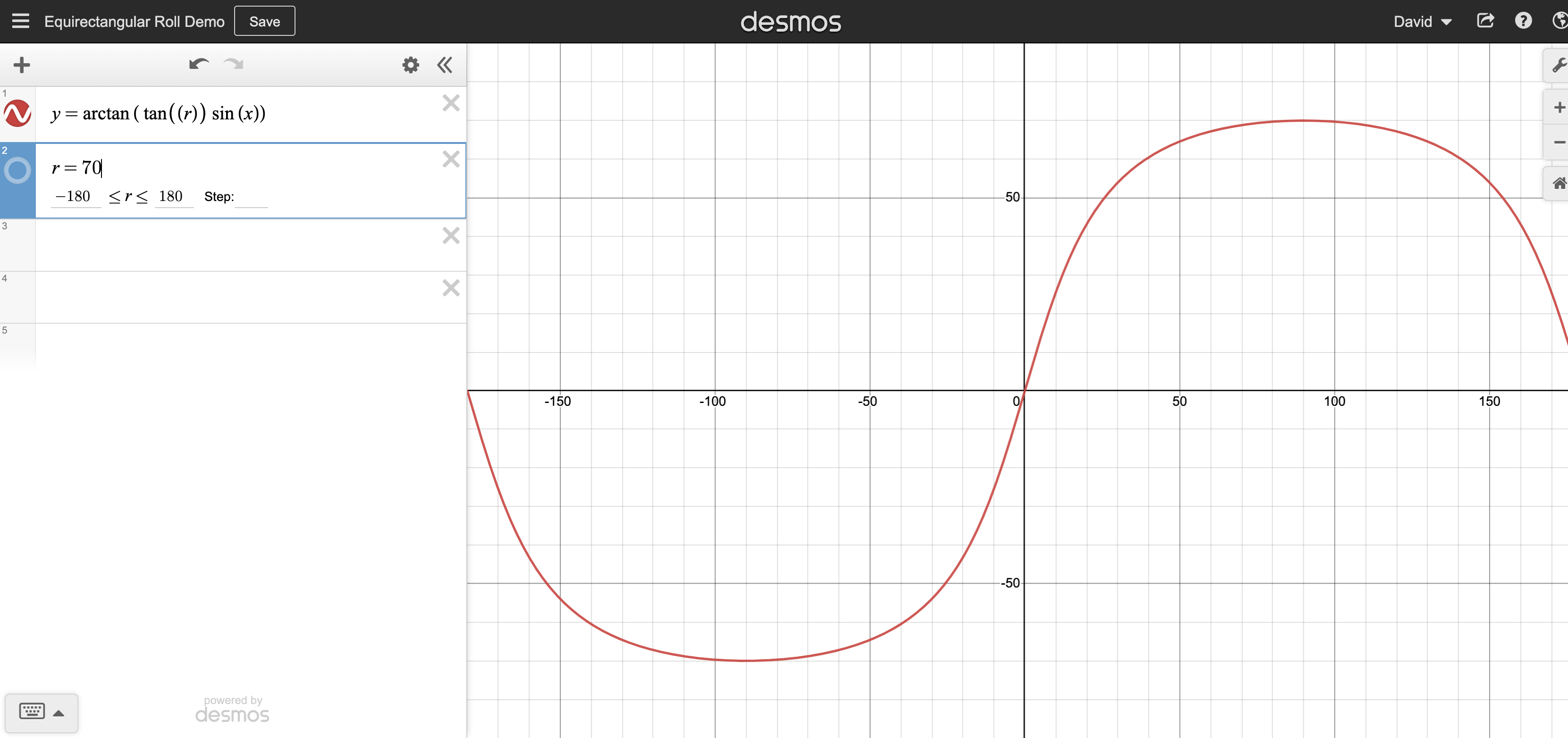
And roll = -110
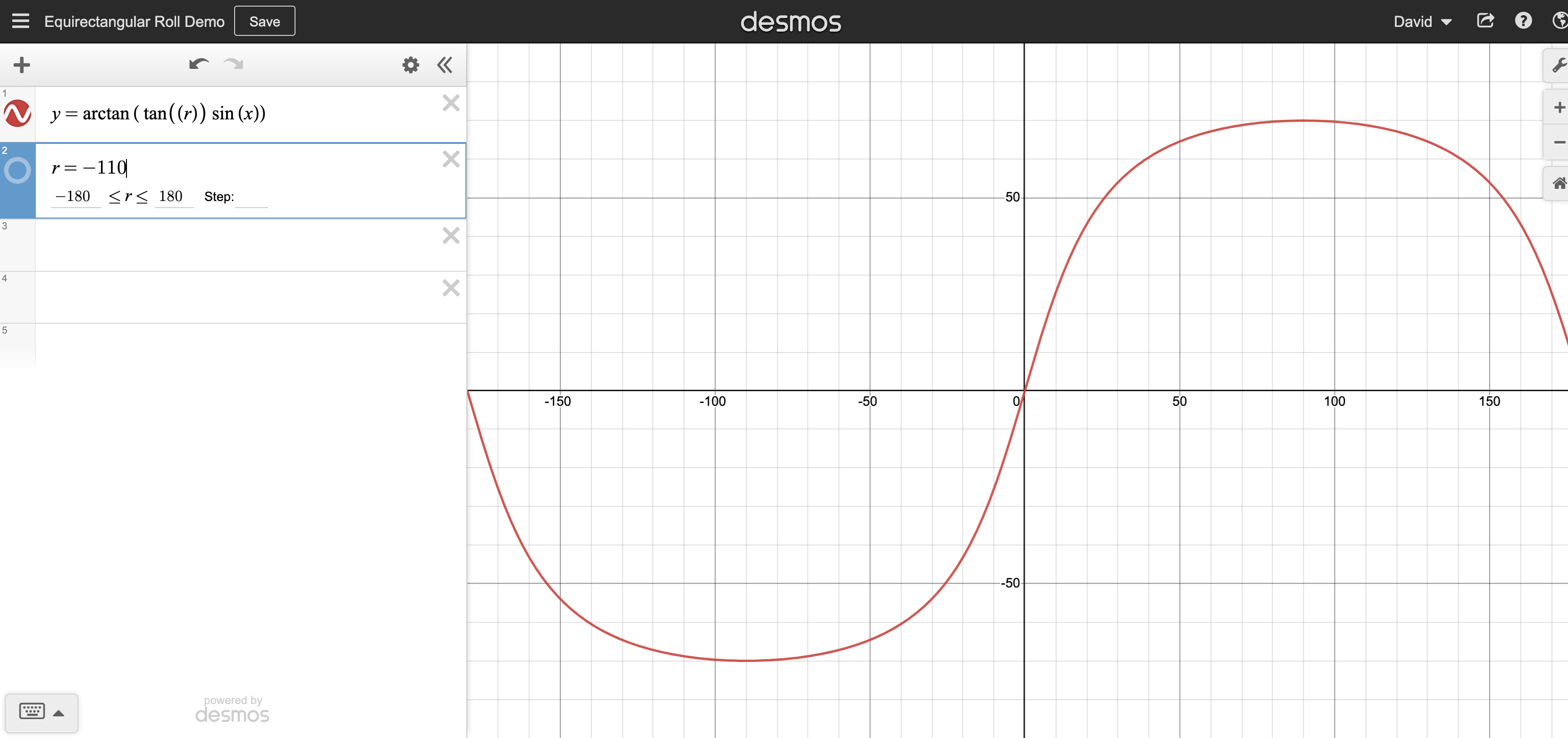
The difference being where the sky (or ceiling) is located in an actual photo.
Remember, in a GoPro equirectangular image we don’t have access to the IMU data, so we need to not only teach the computed to identify the wave, but also the orientation.
By teaching a computer what “upside down” looks like (e.g. sky, orientation of identified objects, etc.), we can also determing this.
Roll and pitch labelling
To start teaching the computer, we need some training data that is labelled with roll and pitch in 360 photos (yaw is not so important). A computer can then start understand what roll looks like using the roll value and the visual of the photo itself.
To do this I used the approach to extract telemetry from a video (and then assign it to extracted images from the same video), as discussed in the post Automatic horizon and pitch leveling of GoPro 360 videos.
However, I was still not 100% confident of the accuracy of my code. Therefore, I also decided to use another training set.
The Ricoh Theta records roll and pitch from the gyro in the photos it produces (in XMP data). Fortunatley, as the Ricoh Theta was released over 6 years ago and was moderatley popular at the time, there are many cheap second hand versions available on eBay (I picked one up for about $50).
Here’s a snippet of said metadata from a photo provided;
  "XMP:PosePitchDegrees": {
    "id": "PosePitchDegrees",
    "table": "XMP::GPano",
    "val": -9.6
  },
  "XMP:PoseRollDegrees": {
    "id": "PoseRollDegrees",
    "table": "XMP::GPano",
    "val": -131.6
  },
Collecting training data
Now for the fun part!
Essentially the more training images labelled with roll and pitch values, and the variety of visual landscapes within them will help make the model more accurate at detecting roll and pitch where this telemetry does not already exist.
We're building a Street View alternative for explorers
If you'd like to be the first to receive monthly updates about the project, subscribe to our newsletter...
