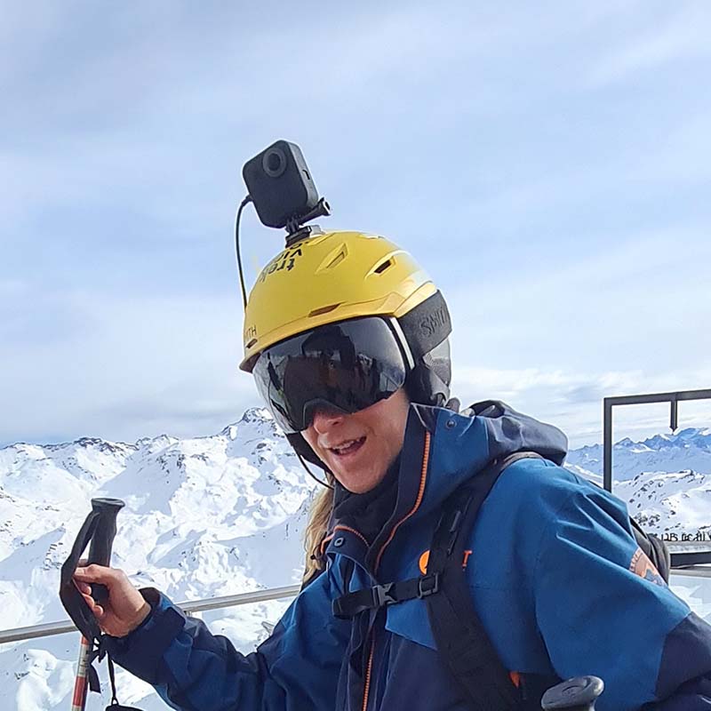
360 Cameras are full of sensors (and not just image sensors).
What was once a device that simply exposed light to film, is now a device that measures light hitting a sensor and a whole host of other things; location, direction of travel, temperature…
In the world of 360 tour photography, these sensors can be particularly important. For example, being able to determine the pitch and roll of the camera at the time of capture can help improve stitching quality (e.g by making automatic horizon leveling possible).
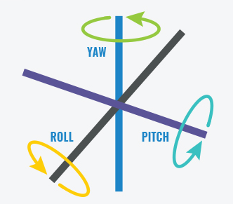
Last year a I explained more about Yaw, Pitch and Roll.
In this post I’ll talk a bit more about how they’re measured by cameras.
Six degrees of freedom
Degrees of freedom (DoF) refer to the number of basic ways a rigid object can move through 3D space. There are six total degrees of freedom.
Three correspond to rotational movement around the x, y, and z axes, commonly termed pitch, yaw, and roll (3-DOF for orientation).
The other three correspond to translational movement along those axes, which can be thought of as moving forward or backward, moving left or right, and moving up or down (3-DOF for position).
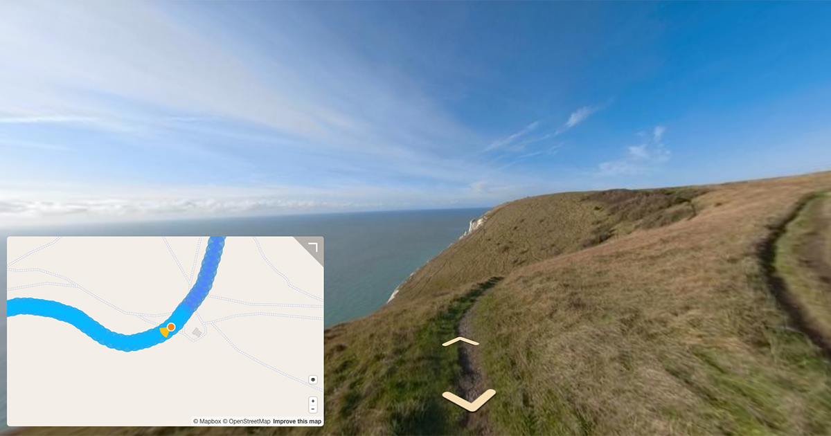
Sometimes you can estimate this information using reported GPS information. For example, calculating pitch, heading and speed between two photos.
As sensors become cheaper, many camera manufacturers are also including sensors that can more accurately measure this telemetry. In order for a camera to be Street View Ready, it requires six degrees of freedom (6-DOF) to be reported.
This information is usually reported by an Inertial Measurement Unit.
Inertial Measurement Unit (IMU)
IMUs, or Inertial Measurement Units, can measure a variety of factors, including speed, direction, acceleration, specific force, angular rate, and when using a magnetometer, magnetic fields surrounding the device.
Technically, the term “IMU” refers to just the collection of sensors inside the component, but IMUs often include sensor fusion software which combines and processes data from multiple sensors to provide measures of orientation and heading. This combination of component and software is also referred to as an AHRS (Attitude Heading Reference System).
An IMU can measure between a minimum of 2 DOF to a maximum of 6 DOF. This is dependent on the types of sensors used.
Most modern IMUs are composed of a 3-axis accelerometer and a 3-axis gyroscope (often called a 6-axis IMU).
Some also include an additional 3-axis magnetometer (considered a 9-axis IMU).
Accelerometer

Measures velocity and acceleration.
The most commonly used type of motion sensor is the accelerometer. It measures acceleration (change of velocity) across a single axis, like when you accelerate in your car or drop your phone.
Accelerometers measure linear acceleration in a particular direction. An accelerometer can also be used to measure gravity as a downward force.
You’ll see Accelerometers reporting data in Meters per Second on GoPro cameras.
Gyroscope

Measures rotation and rotational rate.
It’s easy to confuse accelerometers and gyroscopes. The main difference between the two devices is simple: one can sense rotation (gyroscope), whereas the other cannot (accelerometer).
While accelerometers can measure linear acceleration, they can’t measure twisting or rotational movement. Gyroscopes, however, measure angular velocity about three axes: pitch (x axis), roll (y axis) and yaw (z axis).
When integrated with sensor fusion software, a gyro can be used to determine an object’s orientation within 3D space. While a gyroscope has no initial frame of reference (like gravity), you can combine its data with data from an accelerometer to measure angular position.
You’ll see Gyroscopes reporting data in Radians per Second on GoPro cameras.
Magnetometer

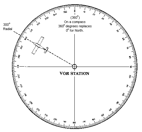
Establishes compass direction (directional heading).
A magnetometer, as the name suggests, measures magnetic fields. It can detect fluctuations in Earth’s magnetic field, by measuring the air’s magnetic flux density at the sensor’s point in space. Through those fluctuations, it finds the vector towards Earth’s magnetic North.
This can be fused in conjunction with accelerometer and gyroscope data to determine absolute heading.
You’ll see Magnetometers reporting data in µT (microteslas) on GoPro cameras.
How 360 cameras report IMU data
[For videos this is written into the telemetry track]. Typically telemetry formats for 360 cameras are reported in two standards, either gpmf (GoPro) or camm (most other cameras).
In the case of image files, the data can be fused together to report additional telemetry (like yaw, pitch, and roll) and then commonly reported in the XMP fields (e.g. [XMP] PoseHeadingDegrees, [XMP] PosePitchDegrees) – although GoPro cameras do not embed any of this calculated data to still images.
We're building a Street View alternative for explorers
If you'd like to be the first to receive monthly updates about the project, subscribe to our newsletter...


